
Extracting illustrations from CAD files for documentation is obvious. Organizations can do this smart and inexpensive by using XML. However, little can be found on the net about this. It is time for an example. For understanding the value for your organization, for learning and or for direct use.
Table of Contents
Part I: What we are going to do and the consequences for business operations.
Organizations with large quantities of library parts in CAD need overviews in PDF format for technical documentation and sales publications. This creates dilemmas:
- Everything must be exported per image from the CAD program and inserted into a word processor or DTP program. If you study PDF files better, you will see that InDesign is popular and that means that someone is processing picture by picture – an expensive hobby.
- The quality of drawings is lost when they become bitmaps, made up of coloured pixels. So we seek refuge in Scalable Vector Graphics, SVG – no pixels but lines. It is shocking to see that if you enlarge a PDF a little, to view details, you will be welcomed with a gray haze that adds nothing. SVGs don’t have that problem.
- Images on the net are almost always bitmaps. It is important to realize that most internet browsers directly support SVG, which means that you can make a substantial improvement in quality.
- Publications are sometimes just not completely finished. You see this very often with publications of products from large companies, such as cars and washing machines. You open the PDF manual, you search in the table of contents, you have to go to page 154 and so you click on the link to 154 in the table of contents. Well, that seldom goes well, no working link and therefore you start scrolling down 154 pages, often incorrectly numbered. This solution (LibreOffice) takes care of that with proper TOC handling.
All in all, there are good reasons for making publications smarter and better.
This topic has become somewhat longer than expected – and is by no means complete. That is why it is split into three parts:
- Part I is intended for business operators and is not technical, part II and III is.
- Part II deals with the translation of CAD files into SVG files.
- Part III deals with creating FODT files that are the basis for publications and of course how you will embed those SVGs.
FODT stands for Flat Open Document Text. This is the uncompressed XML format for text documents from LibreOffice et al. Precisely because you can go in all directions from LibreOffice, think of PDF and MS-Office, the use of FODT offers great automation possibilities.
CAD files can be exported as SVG files in BricsCAD. And all of that can also be perfectly automated. You don’t have BricsCAD? Even the simplest version of BricsCAD can export SVGs and a 30-day trial version can be downloaded free of charge.
So I can already tell you that this method will save you a lot of time and money while offering highest quality. For managers that is important, for the people who implement, the technical details are important. In other words: managers can now stop reading and give this article to the IT staff (or call us). Just read on for a second because another aspect of another order is important.
Anyone who is a little handy can simply put this together in his shed. How can? Ladies and gentlemen, we are talking about open file formats in XML. The following shows how incredibly important open formats are for organizations.
The SVG format is standardized by the World Wide Web Consortium (W3C) and the FODT format used has an OpenDocument format (ODF), standardized by the OASIS consortium.
You can still use XML formats in the 22th century. XML makes you independent of suppliers. Quite important for an organization.
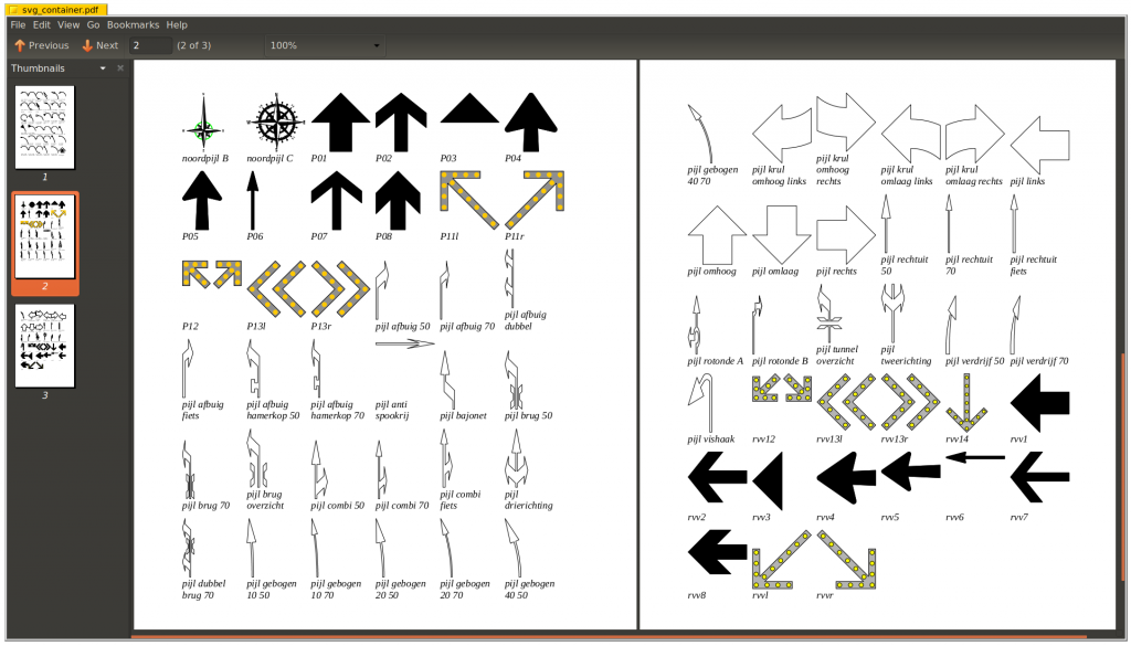
The following is a screen dump of an automatically created PDF that contains CAD drawings with file names:
Part II: Creating Scalable Vector Graphics
There are various ways to extract SVGs from DWG files. In this case a script is created with a spreadsheet. The script is given to BricsCAD. It is smart to always work with a copy of the drawings. A script is interesting for educational reasons because you see how it works. Further automation with Lisp for a more structural solution is obvious.
In BricsCAD > Settings. Search for SVG: You can specify the export format, for example 200 * 200 px and a line weight scale, for example 1 or 2, try & error. Please understand that a value of 400 * 400 px does not influence quality, only size.
In case you want square SVGs, specifying something like 200 * 200 px is not enough. You must also square modelspace. The easiest way is by drawing a square and drag the BricsCAD window borders accordingly, so that the square fits ~exactly before you run the script.
In this example (real life): Folder \trunk\testing\tools\dwg2odt is where the FODT will be located. This folder has two subfolders, svg for exported results and tmpdwg for the parts being converted.
Go to the folder with the drawings in DOS
1 2 3 4 | cd \ C:\>y: Y:\>cd \trunk\testing\tools\dwg2odt\tmpdwg Y:\trunk\testing\tools\dwg2odt\tmpdwg>dir /o/n/b *.dwg > ..\files.txt</code> |
Or, in Linux or Unix (OS-X):
1 2 | you@work:~$ cd /trunk/testing/tools/dwg2odt/tmpdwg you@work:/trunk/testing/tools/dwg2odt/tmpdwg$ ls -1 *\.dwg > ../files.txt. |
Open files.txt and paste the lines in LibreOffice Calc, cell A1. Column A now contains file names.
The script starts with the CAD command “open”, then the file name (A1) and ends with all commands. B1 contains that end with all commands. The following should be pasted in B1:
filedia 0 zoom e export (strcat "y:\\trunk\\testing\\tools\\dwg2odt\\svg\\" (substr (getvar "dwgname") 1 (- (strlen (getvar "dwgname")) 4)) ".svg") filedia 0 (if (> (getvar "dbmod") 0) (command "close" "no") (command "close")) |
Make sure you also copy the space before filedia and adjust the path of course.
C1 contains everything concatenated
="open "&A1&B1 |
Now autofill columns B and C down.
Copy values from column C in Notepad++. Note that there is exactly one blank line at the end. Save as dwg2svg.scr.
Start BricsCAD with an empty drawing.
Enter command script, browse to dwg2svg.scr and go.
That is basically it. You can start with small batches, adjust the parameters and, if you are satisfied, execute the large batch in one go. Control is easy with Inkscape.
Set filedia to 1 again in BricsCAD, filedia is a command. You will think it is strange that filedia occurs twice in the script. That’s right, command “export” spontaneously returns filedia to 1.
This method is extremely rudimentary, a lot of file tuning is possible with Lisp in order to influence the output. Postprocessing of SVG files is also a possibility.
Part III: Creating Flat Open Document Text
Structure FODT
A FODT document is written in XML. Because the files are often so large, the structure is not immediately clear. That is why the XML structure follows here:
1 2 3 4 5 6 7 8 9 10 11 12 13 14 15 | <?xml version="1.0" encoding="UTF-8"?> <office:document > <office:settings> ... </office:settings> <office:scripts> ... </office:scripts> <office:font-face-decls> ... </office:font-face-decls> <office:styles> ... </office:styles> <office:automatic-styles> ... </office:automatic-styles> <office:master-styles> ...</office:master-styles> <office:body> <office:text> <text:sequence-decls> ... </text:sequence-decls> Dit is het deel waar de content staat ... </office:text> </office:body> </office:document> |
When <office:settings> … </office:master-styles> is omitted, LibreOffice adds it automatically.
The line “This is the part with content …” is what we are going to produce ourselves. Syntax errors are showstopper, make sure that opened tags are also closed. An XML-sensitive editor such as np++ is a requirement.
Introduction of XML and SVG
Let’s dive into it. The following is an excerpt from a FODT at the point where a binary saved SVG image ends and another binary SVG file starts.
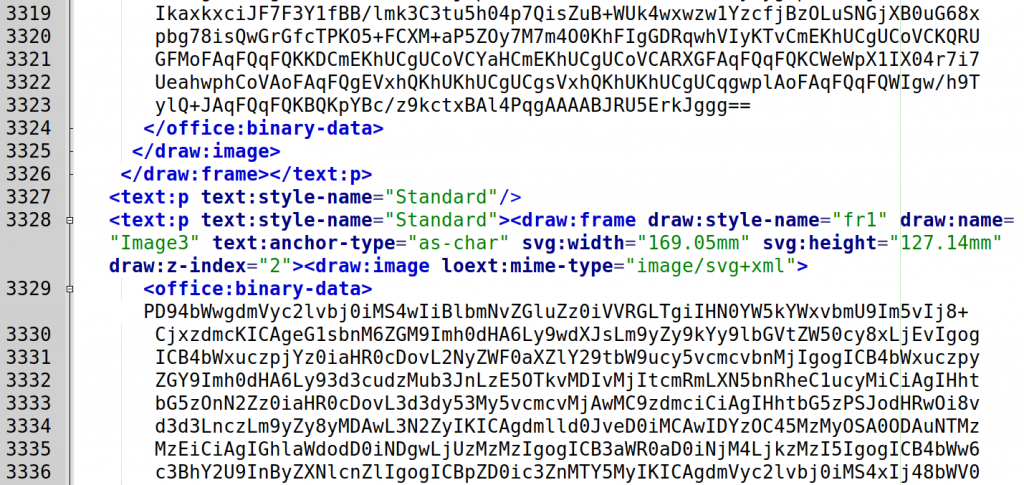
It is therefore difficult, but not impossible, to place those binary files. Lazy us, we choose a different approach: links to the images.
Inserting two SVGs by linking provides the following:
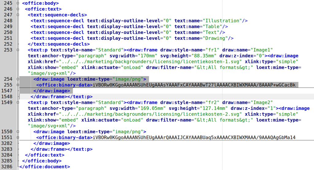
We can see the XML structure, so the tag <office:body> is apparently where all the content is. On line 253 you can see that the SVG file is indeed linked, i.e. relative. Apparently, LibreOffice believes it is important to add a cache in the form of a binary PNG – users lose the linked information, practice shows. Do we need that cache? Testing means throwing away 254 … 1547 and 1550 … 3282.
Whether that works? Hell yes!
And that opens the way for you to get started with shell scripts.
Important to mention, LibreOffice contains an very old and very ugly bug that causes the process of “repagenating” to crash when a lot of images are used. That seems like a show stopper, but this problem does not occur when all images are anchored as a character. XML: text: anchor-type=”as-char”.
Finally, a trick about the corporate identity. You can implement this in the FODT file completely, but then you have the problem that if something changes, you have a lot of work again. Alternatively you can start by using a new standard, out of the box, document. If you link that document to a master document with corporate styles, it will automatically receive the formatting from the master, easy peacy! Of course use the same style names.
Create FODT
We now have many SVGs and they must be included in XML. This is done in BASH and the location used in this example is:
/data/sit/trunk/testing/tools/dwg2odt/svg
You build the document one directory higher, in dwg2odt.
The idea is to concatenate text fragments together, using cat and handle the part with the SVGs with a for loop.
Consider Cygwin if you use Windows, it has been tested and it works fine.
Getting started means saving a blank document as FODT, open it with an editor and save the parts we need.
An example with two SVG links
Look it this screen dump of a piece of document from LibreOffice:
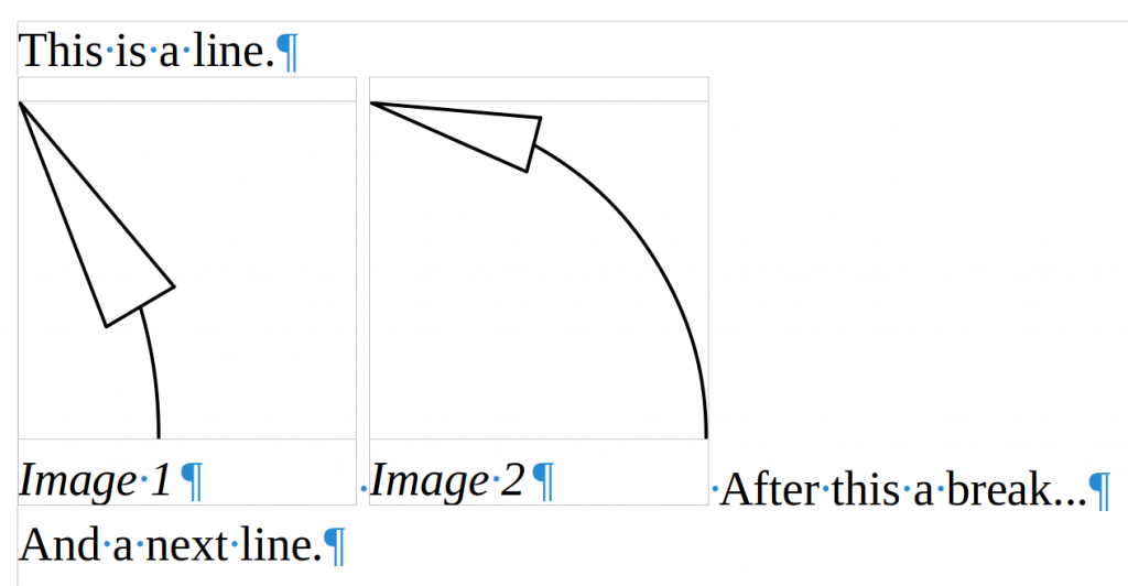
There are three text fragments and two SVGs that are each placed in a frame with a caption, so frame in frame. Don’t be concerned about the layout now, the master document takes care of that.
You see the structure, on line 1 the declaration, line 3 … 556 the document, line 261 … 555 the body.
Look at office:text on 262. , we first get text:sequence-decls on 263. They are also contained in the same way in a new and empty document. That, including tag <text:p …”Standard”> on 270, is therefore the fixed part of everything within office:text. The rest within office:text can be entered by us.
First, we can remove the PNG caches: lines 288 … 407 and 428 … 549
If we ignore the three texts from the screen dump with arrows, what do we have left over? What is variable?
The answer: Everything that falls within tag draw:frame at 270, followed by the space <text:s/>.
The result of this analysis is that you keep a block that repeats itself per SVG. This is block 1:
You can see that story in the following script as argument for the echo statement within the for-loop
The BASH script
A few final comments, as far as you hadn’t thought of them yourself:
- The script is an example, start from your own environment, new ODT file, add some images with links as you want them, don’t forget, anchored as a character, save as FODT, use an editor to get the header “fodt_header” and footer “fodt_footer” (without extension), study and edit the desired XML code of the images.
- Making the intermediate part means tuning and testing the script below. Are you satisfied with the final FODT file? Edit it further as ODT, add it to an ODM file, create PDF files, and so on.
- You can also cut and paste from that new document, but beware, images are still linked. Embedding is done via Edit> Links.
- Remember that you can generate HTML code in exactly the same way for inclusion in, for example, a WordPress site.
- The script contains additional information, you may want to read it.
Finally the BASH code, many comments, little code, paste in your editor…\
1 2 3 4 5 6 7 8 9 10 11 12 13 14 15 16 17 18 19 20 21 22 23 24 25 26 27 28 29 30 31 32 33 34 35 36 37 38 39 40 41 42 43 44 45 46 47 48 49 50 51 52 53 54 55 56 57 58 59 60 61 62 63 64 65 | #!/bin/bash # General, an example script that creates Flat Open Document Text (FODT) with SVG's # We build a file svg_container.fodt with this script... # This is file svg2fodt.sh # This script expects a subdirectory svg with SVG's relative to the current directory where this script runs. # It also expects a file fodt_header and fodt_footer in the current directory. # Create the start cat fodt_header > svg_container.fodt # Make counters # They are used for Frame and Image names and z-indexes, they should be unique and are incremented in the loop. countera=1 counterb=0 counterc=1 # Go to directory ./svg cd svg for thefilename in *.svg do file=$(basename "$thefilename") # ext="${file##*.}" filename="${file%.*}" echo -e " <draw:frame draw:style-name=\"fr1\" draw:name=\"Frame$countera\" text:anchor-type=\"as-char\" svg:width=\"25mm\" draw:z-index=\"$counterb\"> <draw:text-box fo:min-height=\"25mm\"> <text:p text:style-name=\"Caption\"><draw:frame draw:style-name=\"fr2\" draw:name=\"Image$countera\" text:anchor-type=\"as-char\" svg:width=\"25mm\" style:rel-width=\"100%\" svg:height=\"25mm\" style:rel-height=\"scale\" draw:z-index=\"$counterc\"><draw:image xlink:href=\"svg/$filename.svg\" xlink:type=\"simple\" xlink:show=\"embed\" xlink:actuate=\"onLoad\" draw:filter-name=\"<All formats>\" loext:mime-type=\"image/svg+xml\"/> </draw:frame><text:span text:style-name=\"T1\"><text:line-break/></text:span>${filename//_/ }</text:p> </draw:text-box> </draw:frame>" >> ../svg_container.fodt # </draw:frame><text:s/>" >> ../svg_container.fodt let "countera=countera++" let "counterb=counterb+2" let "counterc=counterc+2" done # Go back to directory higher cd .. # Almost finished, glue the ending tags. cat fodt_footer >> svg_container.fodt # About the echo statement... # As you can see, the structure with indentation and line breaks is almost not changed. # Changing structure will influence the final document, line breaks and spaces are added. # So don't or try&error. # That is why the last echo line is commented, it did cause an extra space. # I've tried using a printf statement, instead of echo, # but that had trouble producing something properly when texts get longer. # Echo syntax used: echo -e "a bunch of characters" >> the-fodt-file. # So all "-characters inside XML are escaped like \" # filename is the name without extension .svg. # In particular for Windows users, .svg files are processed, .SVG files are not. # Filenames in linux, unix are case sensitive. # ${filename//_/ } is used to replace underscores in the file name, if you don't # want that, simply use $filename # z-index should be unique. With two frames per echo statement, # two times z-index per echo statement. # That is why $counterb and $counterc are used, incrementing with 2, while looping. # Frame dimensions can be altered directly in this code, here the values are 25mm. # Modify to taste. Really hope it helps you, best regards, Wiebe van der Worp, NedCAD. |