
The resistance of the bodywork of a car… The question is to what extent the resistance of the bodywork is negligible. What is this resistance anyway? If you search for it, you will not find any information. A search for some answers and a surprising conclusion! If you install a high power inverter you probably want to read the conclusions at least.
Table of Contents
Understanding the current flow
If you run a current through a body between two points A and B, that current will not run in a straight line.
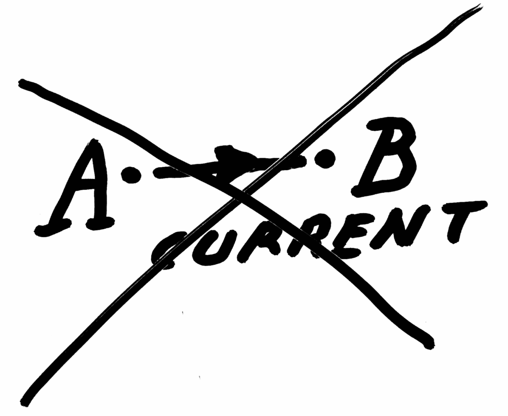
Consider a rectangular sheet: The current will spread out and choose the easiest path without too much electron interference on the way – that is what the electrons told me.
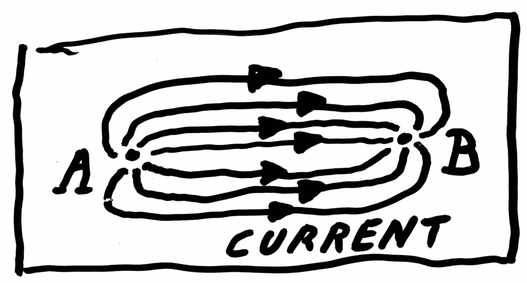
The current density is largest at the points and much less between them.
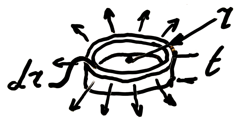
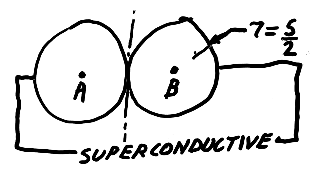
Let us assume two M6 chassis connections. At r=3 mm, a current I passes through a thin ring with a surface SU.
The surface SU is equal to the product of the plate thickness t and the circumference of circle r3.

The model
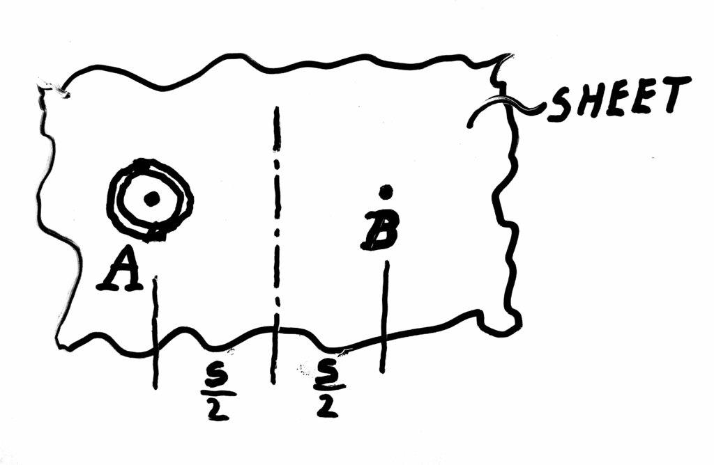
So you could make a model in which the current flows from the first point to the edge of a round plate.The edge of this round plate is then the imaginary projection of the centre line between the two points. From that line, the current flows on to the second point. If two points are 1000 mm apart, the radius of the disc is 500 mm. The current through both discs is equal, the total resistance is the sum of the resistances of the two discs – just like the voltage drop. It goes without saying that the edges of the two discs are imaginatively connected without resistance. This model will be pretty close to reality. Doesn’t sound too crazy, does it?
Practical approach
Mild steel 0.75 mm
What is the specific resistance of mild steel?

$\rho = 15 \times 10^{-8} \Omega . m$
This means that one cubic millimetre has a resistance of 0.00015 ohm. What is the resistance of a ring of 1 mm around r3? Thickness t is set to an acceptable value of 0.75 mm. SU becomes 4.7 * r, so 14 mm2. R becomes 0.00015 / 14 ohm for t = 0.75 mm. More general for r and r + 1 mm, the resistance of a ring with delta r and height t = 0.75 mm:

$R_{1mm} = \frac{3.2 \times 10^{-5}}{r} \Omega$
Numerical solution
A numerical Quick&Dirty approach (spreadsheet, step 1 mm calculations from 1 to 500) is taken in order to calculate the resistance from a point to the middle of that point and another point, defined as 500 mm.
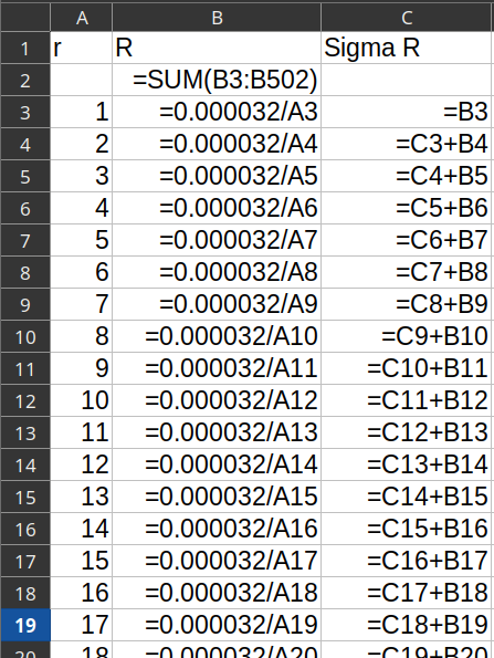
In our case the resistance is 0.00022 ohm. So over 1 meter, R = 0.00044 ohm. That is indeed not much. However…
Mathematical solution
A bit out of my comfort zone: The mathematics of one disc (there are two)…
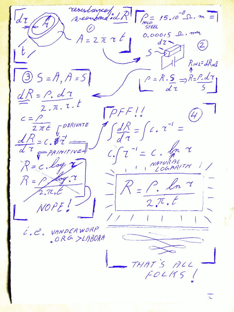
① Geometry
Ring-shaped element in the sheet:
where
𝐴 is the cross-section area, 𝑟 the radius and 𝑡 the sheet thickness.
② Material and element
Resistivity:
(≈ 0.00015 Ω·mm for mild steel).
Ring element of length  and area
  :
:
Differential form
With  :
:
Define  →
→
Non-render example (kept as text):
$\frac{dR}{dr} = c\,r^{-1}$
④ Integration
Next step… But we have twice a disc and r is not distance d between A and B. That one is not hard:
- dab = 2 * r
- Rsigma = Rdisc1 + Rdisc2 = 2 * R
So, the result is:
The formula

$\quicklatex{size=40}\boxed{R_{AB} = \frac{\rho.\ln{\frac{d}{2}}}{\pi.t}}$
Now let’s try to cook the car paint
Next we take a current of 400 A for an inverter. We loose 0.18 V, 70 Watt over that meter of metal sheet and that is not something to neglect!
This will not be a problem for short engine start current or currents of low power devices. However, the result is surprising, alarming in fact, and needs some final attention for sure! Here we go…
Back to our model
You can think of the connection between the two points as an electrical wire with a variable cross-section. It is thickest in the middle. The voltage drop will therefore be greatest at the points, the ends. A question: Where does 50% and 80% of the voltage drop take place? We can calculate that in the same spreadsheet. The answer is surprising:
On the 0 to 500 mm connection (of 1000 mm total), 50% voltage drop takes place in the first 16 mm and 80% drop in the first 125 mm!
Conclusions
- In situations with high currents:
- Never neglect the resistance of a car’s bodywork.
- If you absolutely must use the bodywork, you must have several connections to the bodywork with sufficient space between the connections.
- If possible, do not use the bodywork at all for (high) currents.
- Do not confuse earthing with the use of the bodywork as an additional conductor.
- Consider poor connections due to corrosion of bare mild steel over time.
- Consider galvanic effects on the bodywork as a whole.
- Consider the possibility of enormous heat development at such grounding points.
Some important personal notes
- I would probably create a set of grounding points…
- One contact point for each 50 A
- Distanced at 100 mm at least
- Sized M6 or M8, properly torqued
- Localized on a beam or similar, with enough material thickness.
- Combined, interconnected, as the sole earthing point.
- The method of mounting bolts and washers is of course very critical in this setup.
After asking a review, this thread with discussion is created: https://diysolarforum.com/threads/when-not-to-neglect-the-resistance-of-a-car-body.19924/