
This page is a link from Conversion to eBike.
Choosing cables (multi core) and wires (single core) is important. Cable sizes: Never under-size, that is obvious. But also never oversize without reason.
I made the mistake to try to standardize and keep expenses low. I bought typical PVC (LiY) cable of 1mm2, with lots of strands just to be sure I could use it anywhere, in several colours. An example, my brake sensors are four, two for engine stop and two for tail light. Weight 5 grams. Aluminium holders, weight 20 grams. Cabling from lever to centre steer (only 60 cm), weight 30 grams. Cabling weight is more than the construction! Same for switch box, it is simply too big and one of the reasons is using heavy cabling. Combined in a braided tube, it is simply way to stiff too. So invest here! Below you’ll find considerations, a practical table and connector issues.
Table of Contents
General considerations
- Diameter is
related to current in Amperes (A), while voltage (V) does not play a
role. We talk about DC here:
- A very save maximum from Ohm heat perspective is 5.5 A per mm2.
- Avoiding too much Ohm losses means larger wire cross section.
- A practical approach: The battery pack can peak 30 A and uses 12 AWG wire (~0.5 m) to the controller. This means 30 A / 3.31 mm2 = 9 A/mm2.
- Often heard: 15 A/mm2 is “no problem”. The quotes: You should consider resistance losses.
- This does not mean you need to use thin wires, they break easily. For example, standardizing on 0.5 mm2 / 20 AWG where 0.21 mm2 /24 AWG is required does not have to be a bad idea.
- Shielding material of wires:
- Silicon shielding is more temperature resistant than PVC (LiY)
- Silicon shielding is easier to bend
- PVC shielding is in some cases – sometimes not – slightly more resistant to wear and external forces.
- Price of silicon rubber cable is higher.
- Strands: many strands make wires flexible and stronger at the cost of a bit larger diameter (copper and air, which both can be ignored).
- Multiple colours make your work much easier, less error prone.
- Multi core cables are interesting for smaller currents.
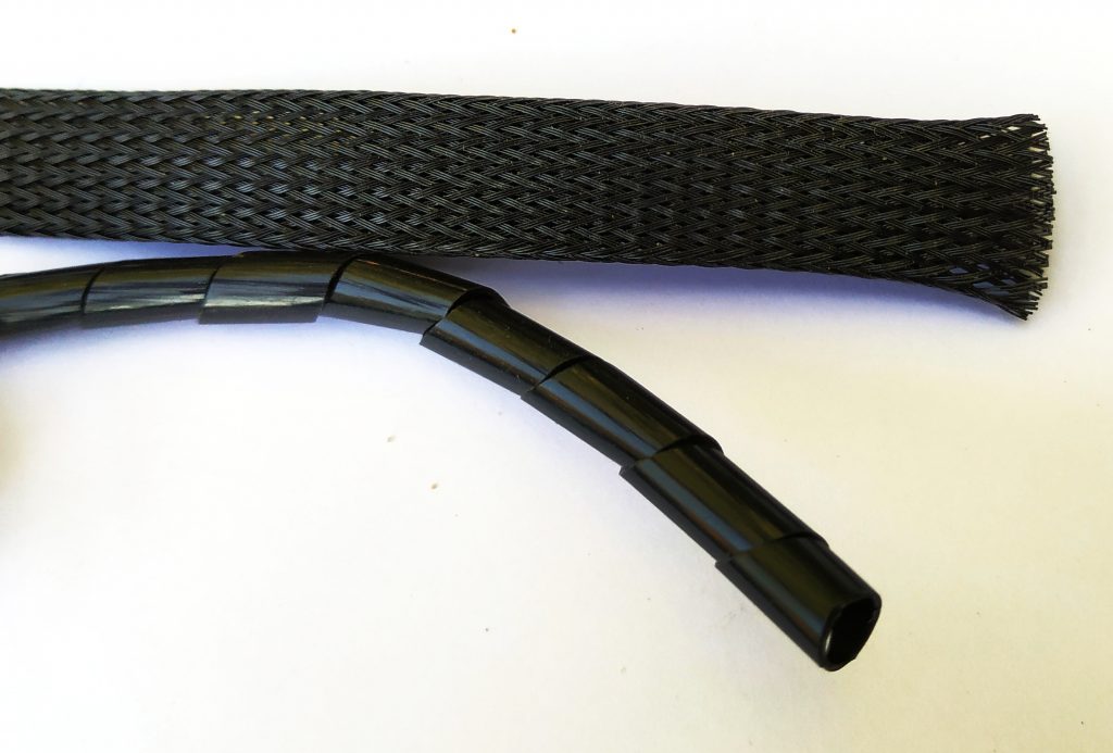
- Braided housing of cable packs are okay, as long is you keep some slack. Otherwise, the pack is not flexible any more. Use shrink tubing at start and end. Spiral cable housing is more ad hoc, last resort.
- Consider to extract a representative wiring drawing from a schema before you start making.
A practical wire diameter table
Suppose, I send 5 A over a 1 mm2 wire for a 250 W, 50 V, ohm device, then we talk about 10 ohm. If you consider the wire 1 m long, it is 0.017 ohm/m and you use a plus and minus wire, then you can conclude the wire has a loss of =2*0.017/(2*0.017+10), 0.34%. So 0.34% of 250W are used for heating up the wires. That is 0.8 Watt. We can neglect that in this case and the wire choice is okay. Let’s translate that to some AWG sizes for 50V bikes:
| AWG | mm2 | I(A) | P(W) | Example | Colour |
| 8 | 8.4 | 41.9 | 2092 | Battery cable | black, red |
| 10 | 5.3 | 26.3 | 1315 | Battery cable 1500W engine | black, red |
| 12 | 3.3 | 16.6 | 827 | Battery cable | black, red |
| 14 | 2.1 | 10.4 | 520 | Charger 10A | black, red |
| 16 | 1.3 | 6.6 | 327 | Charger 6A | black, red |
| 18 | 0.82 | 4.1 | 205 | main distr. wires to front | black, red |
| 20 | 0.52 | 2.6 | 129 | main distr. wires to front | black, red, coloured |
| 22 | 0.33 | 1.6 | 81 | heavy device wires, high beam | coloured |
| 24 | 0.21 | 1.0 | 51 | device wires, high beam | coloured |
| 26 | 0.13 | 0.6 | 32 | short switch wires | coloured |
| 28 | 0.08 | 0.4 | 20 | — | |
| 30 | 0.05 | 0.3 | 12 | — | |
To end with, if we don’t do 5 A over two 1 m wires of 1 mm2, but 10 A and 20 A? Then 0.8 W becomes respectively 3.4 W and even 13 W wire heating. x is the loss rate. The last column l is equivalent cable length…
| I | P | x | l |
| 5A | 0.8W | 1 | 1 m |
| 10A | 3.4W | 4 | 25 cm |
| 20A | 13W | 16 | 6 cm |
Wire connections
There are many options. For example, take a look here. There are signal connectors and power connectors and even in between connectors (hybrid). There are also connectors you can use for both, like GX connectors.
Choosing a connector is based on your needs, like how many Amperes? What does it cost? How often connect and disconnect? One, two or even more poles? Even something like how hard it is to do emergency repair in the field are valid arguments, soldered connections are an example of this. To keep the monologue short, I’ll show you what I used for what, here we go.
A word about the use of shrink tubes
Functions:
- Isolation
- Securing
- Based on shape, and additional
- By using glue
Considerations:
- Loose applied 3:1 ratio shrink tube results in
- more isolation thickness
- better fixation (main wiring)
- better embedding of sharp corners
- Fitted 3:1 and 2:1 shrink tubes result in
- smooth connections
- Securing means connectors are not only isolated, but are also not able to disconnect easily.
- Glued shrink tube may be a bit harder to remove but security is better
- Braided tubes with wires inside, secured on both ends with glued shrink tubes are a nice solution.
Permanent soldered connections
For high current wires a powerful solder iron is needed (old fashioned like 100W). Used for extending wires. From component to component connections are better made with connectors. Keep soldering times short. Of course soldering connectors is obviously required, but for wires:
| Pros | Cons |
| Cheapest connection | Shielding is extra step (shrink tube) |
| Easy to make | Not easy to disconnect |
| Most reliable | |
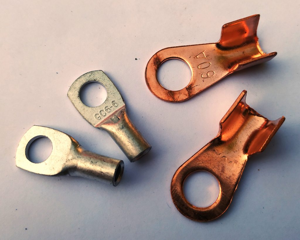
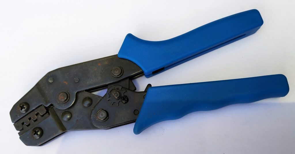
Semi permanent with lugs
Copper or brass lugs have their current rate often written on the lug. Examples: connecting a main switch, connecting BMS main conductors. You may want to use a brass threaded rod (like M6) and brass nuts for connecting lugs. Alternatively, galvanized or stainless steel bolts and nuts are possible as long as is realized that they don’t conduct electricity as well as brass and copper. Finish with shrink tube for isolation.
| Pros | Cons |
| Easy to make | Shielding is extra step (shrink tube) |
| Most reliable | Moderate easy to disconnect |
| | High current connectors are easier to service. |
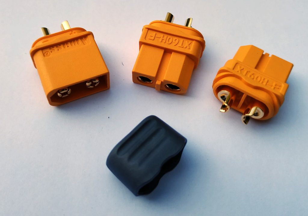
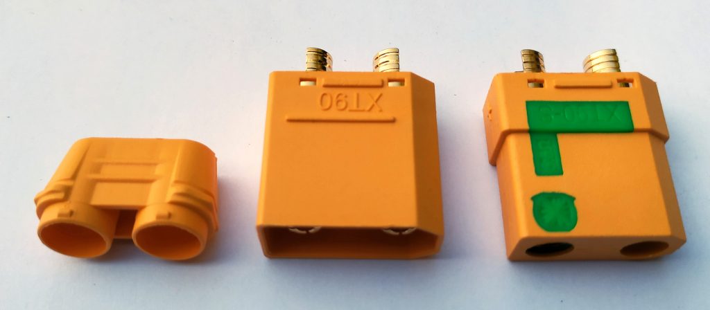
XT connectors
They are popular, they are cheap and able to conduct impressive currents. Types are from small to big: XT30, XT60, XT90 and XT150. The number is the maximum current. XT150 is a single pole connector, see banana’s below. The smaller ones are + and – connectors. XT90 knows a variant with spark protection and it is advised to use that one. Tip: When soldering, first connect male and female. This way the warm pins stay better aligned by the cold pins. Solder quickly.
| Pros | Cons |
| Easy to make | Be careful not to apply heat for to long |
| Very reliable | |
| Easy to disconnect | |
| | High current connectors are easier to service. |
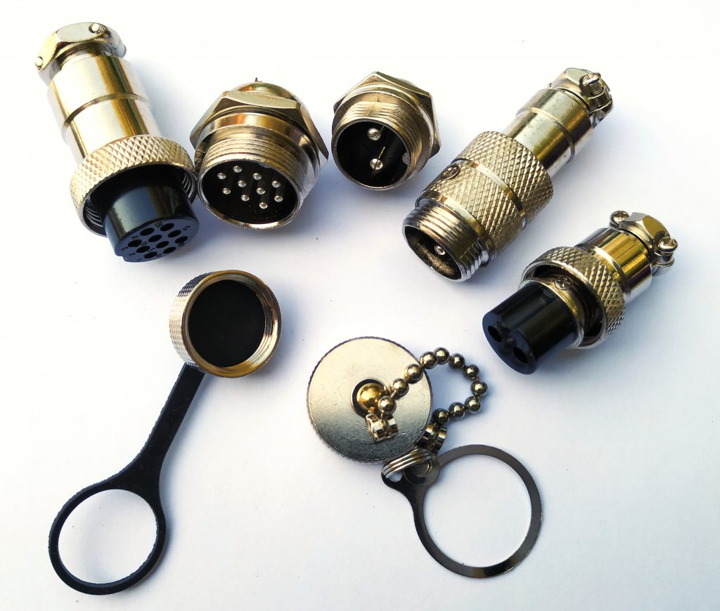
GX series
Connectors of type GX-16 and GX-20 are quite large. They are useful for connecting a cable harness with both signal and (limited) current wires. However, they are best known for connecting to a charger. Pin diameters vary, depending on how many pins the connector is. For each pin it is advisable not to transport more than 5 A. A four-pin connection can therefore be used in combination with a 10 A charger, larger pins can transport 7 A. In that case GX-20 is more obvious than GX-16. The number can be used as diameter for holes, but the thread for GX-16 and GX-20 is M16 * 1 and M19 * 1 respectively.
| Pros | Cons |
| Great for inside / outside connections | Relative heavy and taking much space |
| Limited water resistance | Not suitable for currents over 5 A per pin. |
| Easy to make | |
| Very reliable | |
| Made for many and easy connect and disconnect cycles | |
| Securing without tools, extra materials | |
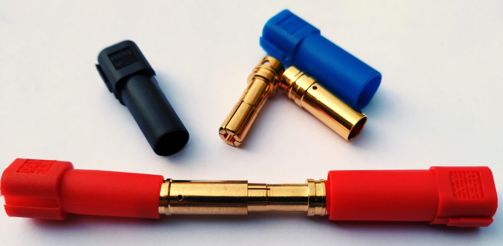
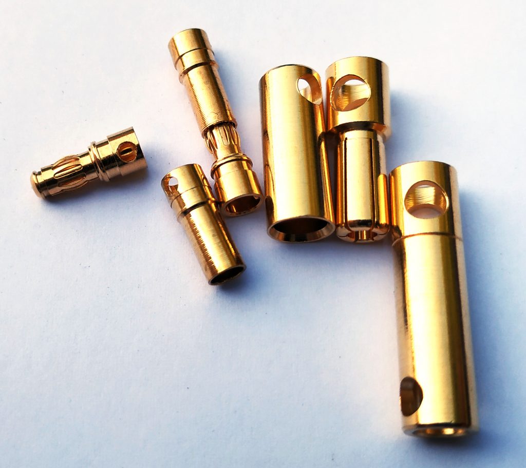
“Banana” series
There are many, many variants that are not standardized. That makes them a bit tricky, check if rigid. Size is determining current rates, but if they slide very easy in and out, consider that a warning. What makes them very attractive is the small size and being in line. Colour, mark your wires very well. For main currents you may want to use XT-150 (which is also a kind of “banana”) or XT-90. For small currents and signals, the smaller sizes are a proper alternatives for legacy automotive connectors.
| Pros | Cons |
| Smallest possible in line connection | Not properly standardized |
| Both signals and high currents | Shielding is extra step (shrink tube) |
| Easy to make | Check if robust per bought series |
| Low prices | Very reliable to unreliable (always check) |
Other connectors
It may be interesting to look for so called Anderson poles (single) or connectors (dual). They have high current rates. Alternatively, several solar connectors are able to connect relative high currents in combination with a water resistant plug construction and low pricing.

This article was excellent and very informative .Does having 1 long wire from end to end better then having to have a few breaks in a wire that is reconnected 3 times from end to end? Does it weaken the voltage or amperage in a connection?
It certainly does. That is why I am a fan of soldering in many cases. ECR or Electrical Contact Resistance is low on proper and clean contacts. However, corrosion en dirt can cause ECR to rise and generate serious heat risks.