
This page provides solutions and background information on making blanks or, more specific, flattening a ruled surface. There are quite a few applications. Consider, for example, blanks of a spiral drill for ground drilling, wood or metal plating in shipbuilding and curved walls and ceilings in architecture. In my humble opinion, the subject is totally undervalued. Time to change that! The objective is to get a powerful tool so you can get started with BricsCAD. In fact, it should even work on BricsCAD Lite because Lisp is supported. AutoCAD LT doesn’t support Lisp but AutoCAD probably works too, not tested.
Warning! The current code does not yet contain a solution for apparent intersecting faces, see “caveats”. So be careful and always check results.
This solution can only be used on ruled surfaces. It is like: If you can bend a model with paper – and you can do very creative things with paper – then this subject deserves your attention. It is surprising what you can do.
The subject deals with a lot and the structure is like stray notes – sorry for that. Therefore: Use the table of contents to navigate.
Feel free to leave a comment!
Table of Contents
The gallery or “Is it free?”
FlatMesh is free to use for you. Free doesn’t exist? That is right. If you use the code, send some photos of blanks, semi-finished or finished products. Others – and that includes me – learn from it. Is that a good deal?
Global information
Introduction
Chronic itches… Through the years it was a wish to come up with something like this but… Time is almost never my friend! Do you recognize that? While coding a project recently, I thought: “Hey, this is close to that almost forgotten project” and so I started this page.
It turned out to be a bit harder than expected. For details, see the accompanying post “Applied Mathematics concerning CAD Faces” – all you ever wanted to know about faces.
If you look at the pictures on this page, you’ll understand why it is interesting. Feel free to use the code and have fun with it. If you think you can improve something, you’re more than welcome, leave a comment.
Is this surface developable or not?
First: What is a developable surface? I am Dutch and would rather say de- or un-wrapable, “afwikkelbaar” (Dutch) but math people talk about “ontwikkelbaar” (Dutch). Translated, it boils down to unwinding, unrolling, unwrapping. Germans say “Abwickelbare Fläche”. The answer is as can be inspected: See https://en.wiktionary.org/wiki/d%C3%A9velopper explaining “veloper” means “wrapping”. Now you know also where “envelope” comes from and what it means.
Long story short: If you can make it from sheet, without stretching and only bending, such as paper or metal sheet, it is developable. Why should it all be so hard?
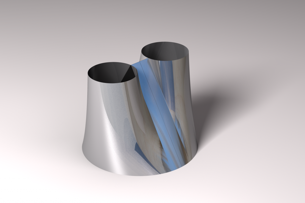
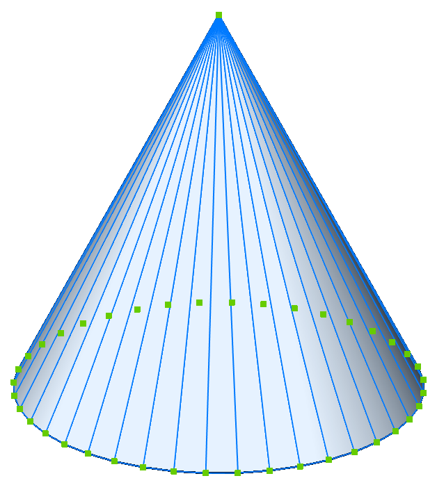
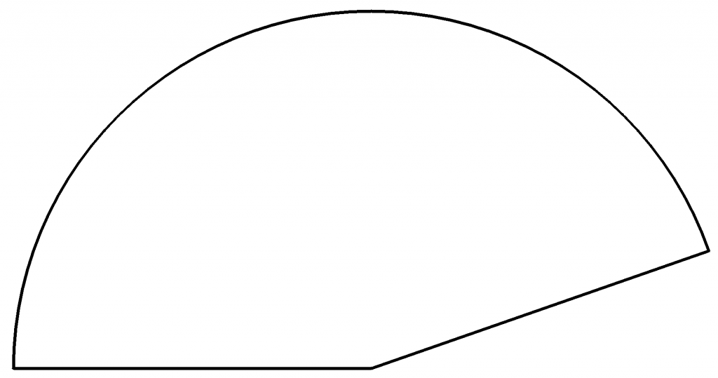
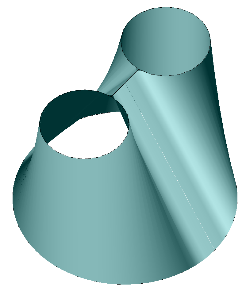
A cone illustrates this very well:
The ruled surface
Considering the above cone: Can you imagine you take a piece of clay and than move a ruler over two guides? One guide curve is the bottom circle, the other one a miniscule nano circle on the top.
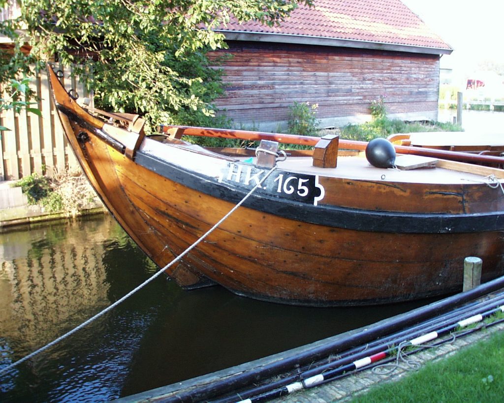
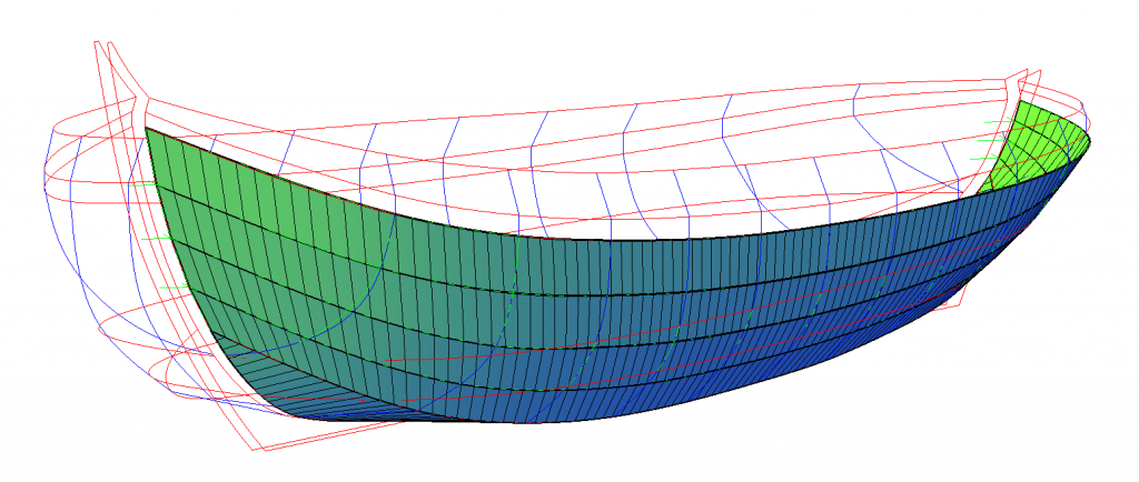
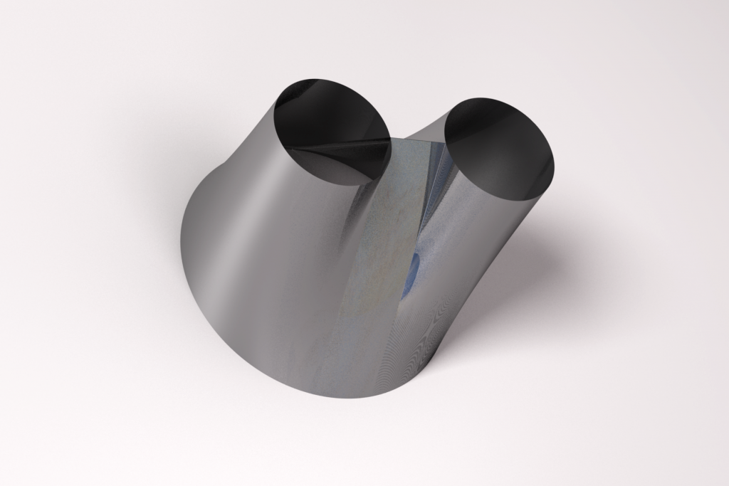
That principle is applicable to whatever guide curves you choose. So let’s have another example:
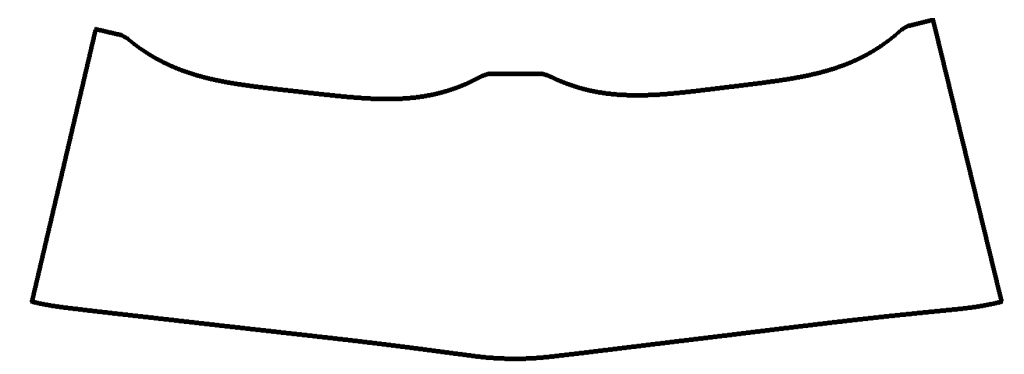
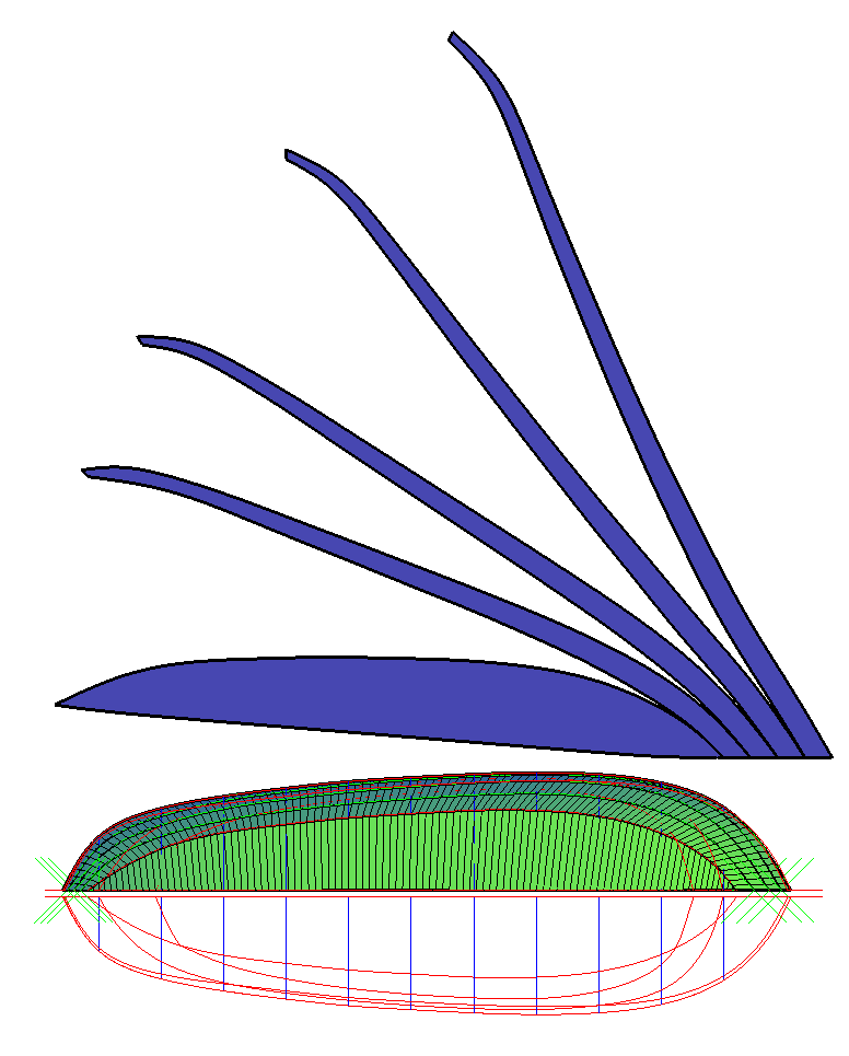
Impressive? I thought so, a complex shape made from a sheet of whatever.
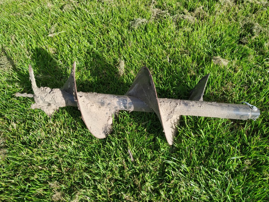
But: Not all ruled surfaces are developable surfaces, not all developable surfaces can be made in one piece. For example:
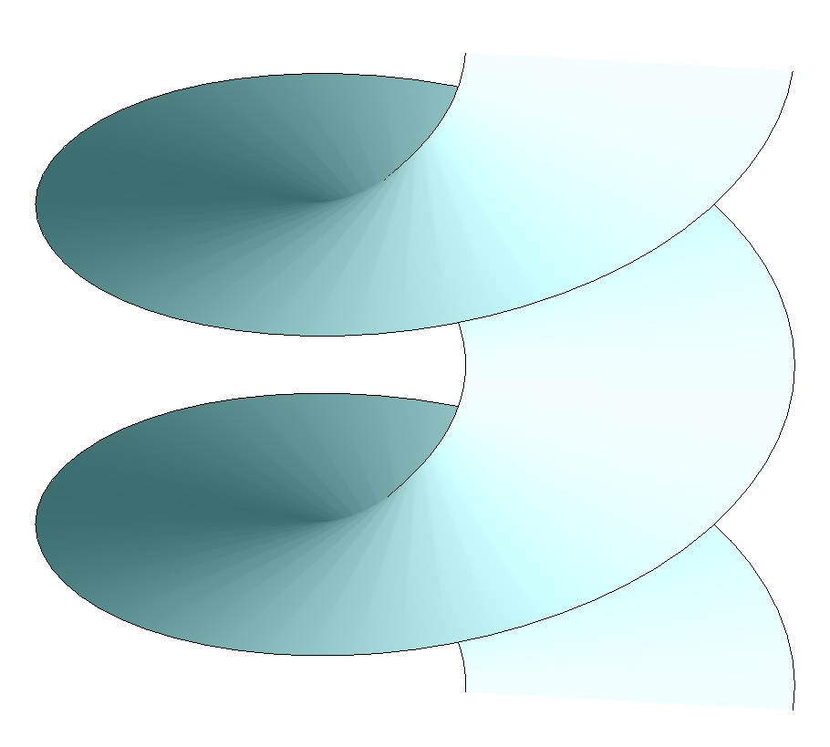
In this case the blank will intersect with itself – that is why there are often welds visible on these kind of spiral drills.
Last, not least, neutral lines
Probably obvious but important: What you construct with this toolset are basically neutral lines, or better, neutral planes.
The neutral plane of a real blank is the imaginary plane that does not shrink or extend when bending the blank. From the inside of a bending, it typically lies between 30 to 50% of the material thickness (K-factor).
Switching bending direction also switches the location of the neutral plane. Quick and dirty assuming it is always 50% is attractive in many cases – if tolerances tolerate it. In that case you have to offset the mesh 0.5*thickness to both sides. Stated more practically, just make sure your two open guide curves are positioned properly before applying a RuleSurf command.
CAD commands
- Making a ruled surface mesh can be done with command
RuleSurf. You select two guide objects like splines and next a mesh is created as if a ruler is equally moved over the guide curves.- Make sure you set
'Surftab1to a proper value. This value is the amount of faces. - Curves may not be closed.
- That implies there is always a (straight) start side and end side of the blank.
- When selecting the guides, take care to select the corresponding beginning sides of the guides.
- Make sure you set
- Next thing: Is it a proper mesh? Internally it should be a
polyline(yes, really, withflag 64set, forget that). How to retrieve that information? Properties should state “Polygon Mesh” with “M vertex count” equal to2. - That leaves the Lisp-command
FlatMesh…
How FlatMesh works
In short
Issue the FlatMesh command and select a proper mesh. That is it. You’ll get a flat blank.
Background information
You already have a fair idea of how it works. The Lisp code extracts the 3D coordinates of each vertex. Those coordinate lists are converted into an ordered coordinate list for each guide or rail, two in total. All we can determine is the distance between successive 3D-coordinates. With that information, the coordinates are flattened to 2D.
Therefore, the mathematics around a triangle with known sides is important. The Lisp code contains a loop that translates the coordinates into new ordered coordinate lists and rebuilds the mesh coordinates, but with z = 0 and flat triangles. Easier said than done but, in hindsight, not too difficult either.
Caveats
- It is a lot of calculation to get a blank and sub results are cumulative, so error margins are cumulative too.
- Use your logical sense, like: “Is this result reasonable?”, like always in life.
- About the amount of faces in a mesh:
- Use
SurfTab1to set the amount. - Too few faces in the mesh will result in an undersized blank without smooth boundaries.
- Too many faces in the mesh will impact the amount of calculation errors.
- Experiment with different values of
SurfTab1and project the resulting blanks over each other. - You’ll notice, for example, that the cone on this page has a very reasonable quality with 100 faces.
- Use
- If guides contain sharp edges, you should check the blank at those corresponding points. For editing,
explodethe polyline,zoomin deep enough, do afilletcommand withradius0and usejointo create the polyline again. - Beware of intersecting faces – both 2D and 3D. This version of
FlatMeshdoes not take this into account and blanks will contain errors.

Qualitative mathematics
For details, see the accompanying post “Applied Mathematics concerning CAD Faces“
Algorithms
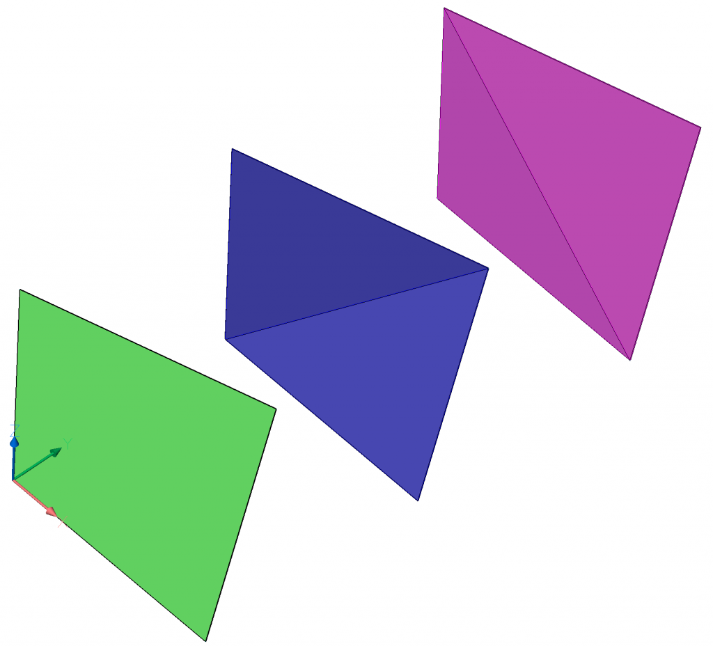
The only challenge is the used algorithm. A 3D-face (green) of a ruled surface is made out of a set of two triangles – or the blue or the magenta variant. Triangles are needed because the corner points of a 3D-face (almost) never lay in a common plane.
How about rule of cosine?
When two points of a triangle are known, just like the distances between all three points, several algorithms can be used, see below.
The challenge is to reduce the error margin. For example, using rule of cosine for a triangle that has one very short and two very long sides – which is almost always the case – introduces a small error. With a Surftab1 value of 100, this error is magnified. That is why testing FlatMesh and getting things right is more work than the actual programming.
Although the rule of cosine is tempting because it is easier than what is below, the drawbacks should keep us from using it in this case – I’ve learned the hard way.
What is the alternate algorithm?
Here are two blue meshes, representing the flat blank of two red curves – all 2D:

The used algorithm is based on the Pythagorean theorem for calculating C and D with A and B given. It is easy to calculate distances between 3D-points and those distances are all we need (and all we have) to do the job.
The left mesh is a special case with A and B similar, we’ll skip that one for now and focus on the right example.
These are the possible varieties:

Discussion about calculation of D is skipped because it is similar to calculating C. That leaves us with the left two variants. Don’t worry, I did put the coding for D in the program 😉
UCS command
One could also use a style where switching from object UCS to world UCS is applied in a loop. It is really quick and dirty – for example, you don’t want (command …) functions in your code. However, it could work.
Quantitative mathematics
For details, see the accompanying post “Applied Mathematics concerning CAD Faces“
The steps
- Calculating
Cis step one – based onAis(0,0)andBis(p,0). - Then there is D. Is D under or above AB?
- However
AandBare not horizontal aligned. Therefore the rotation ofCrelative toAis calculated, based on angleAB. - As a last step, a translation is needed because
Ais not(0,0). - This procedure is a loop for every next point set where not only D, but also C can change from under or above axis AB. Enough complexity I think.
Get the code
Read this first
Understand the caveats, see TOC.
Understand how to use it, see TOC.
There always may be circumstances where the results are not what you expected. FlatMesh is not a polished and fool-proof product. That does not make it less valuable.
However, if you want added functionality, I can always give you a quote.
Feel free to leave a comment if you find a bug.
The code contains several possible algorithm implementations. At the bottom of the code you can switch between them. However, I would suggest you keep it as is.
For readability and educational value, the code is not optimized for speed. Though Lisp is interpreted, it is low level, close to processor instruction sets. Therefore, I expect it to be processed in a blink of an eye.
Downloads
Bugs Feature requests
- With common start point of guides the first point set is not calculated correctly. > Solved.
- In cases with sharp creases in the 3D model, guide that are at some points perpendicular, expect trouble. If a guide is smooth and the blank contains sudden changes of direction, you probably hit this situation.